Hello, welcome to Nanjing Bai Sheng Glass Technology Co., Ltd. official website!

 400-6567763
400-6567763


With the continuous improvement of national environmental protection standards, NOx was included in the binding index system for the first time during the Twelfth Five-Year Plan period. This year, in addition to strict requirements and rectification deadlines for thermal power, environmental protection departments have also attached importance to building materials industries such as cement and glass. In the flat glass industry, some manufacturers have installed SCR denitration devices, and the effect has reached the requirements of GB26453-2011. However, due to the overall downturn in the glass industry, denitrification and emission reduction work has also been affected to some extent. Analysis, comparison and precipitation summary of existing necessary denitration technologies in glass industry.
Present situation of air pollutant emission in flat glass industry
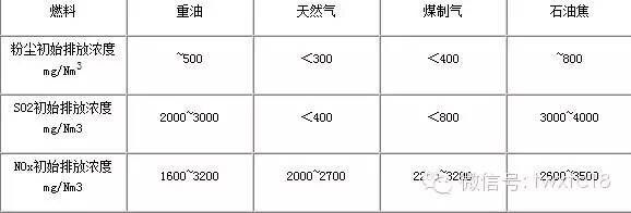
The glass industry started later than thermal power and other industrial furnaces in dust removal and desulfurization. According to the investigation, some flat glass factories still have no effective dust removal measures. In the early stage, most domestic flat glass manufacturers used heavy oil as fuel, and a few used natural gas, coal-to-gas and even petroleum coke. Due to the diversity of fuels, the pollutant emissions of different kilns are quite different. See the picture below.
Table of Original Emission Concentration of Pollutants in Flue Gas of Flat Glass Kiln (standard temperature and pressure, 8%O2)
With the promotion of energy conservation and environmental protection policies and the improvement of environmental protection standards, some enterprises are actively doing the work of changing oil into gas.
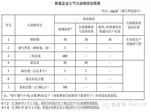
Figure 2 Emission Standard for Air Pollutants in Flat Glass Industry GB26453-2011
Mature technology selection
2.1 Dust removal technology
Mature glass kiln dust control can choose electrostatic precipitation, bag precipitation, wet precipitation and other technologies. The selection of dust removal technology will be determined according to the applicable process of the project. If wet desulfurization is selected, wet dust removal will have better synergistic adaptability.
The performance table of various dust removal technologies is as follows.
2.2 desulfurization technology
In the desulfurization scheme, mature wet desulfurization (double alkali method, limestone gypsum method), semi-dry method and high temperature dry method can be selected. The successful application schemes in wet process include double alkali method, limestone gypsum method, MgO method and ammonia method. According to the investigation, double alkali method and limestone gypsum method have advantages in operation cost and operation and maintenance. In addition, the simplified application of desulfurization technology can meet the requirements of quenching and tempering of glass furnace flue gas.
2.3 Denitrification technology
The mainstream technologies of denitrification include selective catalytic reduction (SCR), selective non-catalytic reduction reaction (SNCR) and wet denitrification. SCR is a technical method proved to be suitable for denitration in glass furnace; SNCR can not be applied to glass industry; The efficiency of wet denitrification is low (< 40%), which can not meet the requirements of glass denitrification alone, so it is used as a combined technology in wet desulfurization application.
The application of SCR technology is limited by the technical development of catalysts. The first application is medium-temperature catalysts (temperature between 270℃ and 400℃), and the more suitable low-temperature catalysts (temperature below 180℃) are still in the research and development stage.
3 glass furnace pollutant overall emission reduction process
Considering the overall process of collaborative treatment of glass furnace dust, NOx, SO2 and other pollutants, the overall design of the process scheme. The following process plan is selected according to the kiln output, existing production line technology, technical applicability and cost.
3.1 Waste heat (power generation) boiler+high temperature electrostatic precipitator +SCR process
The flue gas (about 350℃) led out from the outlet of the waste heat boiler is reduced to 30mg/Nm3 after passing through the high-temperature dust collector, and then enters the SCR denitration reactor. Under the action of catalyst, the injected reductant reduces NOx to N2 and H2O, and the flue gas is returned to the low-temperature section of the waste heat boiler for continuous utilization. The process diagram is as follows:
Process considerations, advantages and disadvantages:
This process is suitable for glass kilns with natural gas or coal-made gas as fuel, and for kiln processes with waste heat to generate electricity. Because of the high temperature dust removal, dust and NOx can be reduced at the same time, and the system occupies a large area, so it is difficult to transform the old line, and the temperature drop of the system is generally less than 20℃.
3.2 Waste heat boiler+conditioning (cooling) tower+high temperature electrostatic precipitator +SCR
The flue gas from the flue outlet of the glass kiln first passes through the quenching and tempering cooling tower, and after cooling and tempering (pre-desulfurization), the flue gas enters the high-temperature dust removal, and then enters the SCR denitration reactor to synchronously complete the dust removal, denitration and desulfurization treatment as required, and the flue gas returns to the low-temperature section of the waste heat boiler to continue the waste heat utilization. The process diagram is as follows:
This process is suitable for glass kilns with heavy oil, petroleum coke and other fuels, and is equipped with waste heat power generation boilers. The flue gas conditioning tower installed in front of the dust collector is the key to increase the dust removal effect. When the conditioning tower is used as pre-desulfurization treatment, the temperature drop will reach 30℃. However, due to the clean energy transformation in the glass industry, the kilns that use heavy oil and petroleum coke as fuel in the later period are gradually replaced by natural gas.
3.3 desulfurization conditioning+high temperature dust removal +SCR denitrification+heating waste heat boiler
The flue gas from the flue outlet of the glass kiln first passes through the desulfurization conditioning tower, and after temperature reduction and desulfurization treatment, the flue gas temperature is controlled at 320~380℃, then enters the high-temperature dust collector, then enters the SCR reactor, and then enters the heating waste heat boiler, and the flue gas temperature at the inlet of the waste heat boiler is ensured to be greater than 300℃ through early temperature control. According to the process requirements, a bypass flue is set in front of the waste heat boiler to achieve desulfurization, dust removal and denitrification simultaneously. The process diagram is as follows:
This process is suitable for glass kilns with small output ratio, such as boiler systems below 300t/d, which do not use waste heat to generate electricity. This kind of glass kiln, because of its small output and early construction time, is mostly a calendering and special glass production line, which needs to deal with a small air volume (below 60,000 nm3/h). It is easier to realize the layout of new equipment through on-site optimization and overhead.
3.4 cooling+high dust SCR+ heating boiler+wet dust removal, desulfurization/semi-dry desulfurization system
The flue gas at the exit of the main flue of the glass kiln is cooled (sprayed with water) to control the temperature of the flue gas at about 350℃, and then passes through the SCR denitration reactor with high dust. After the waste heat is utilized, the dust in the flue gas is washed by wet dust removal, which has a preliminary desulfurization effect, and then enters the wet desulfurization, wet dust removal and desulfurization process related equipment for sharing. When the semi-dry desulfurization system is used, it will be more conducive to the treatment of dust. The process flow chart is as follows:
This process is suitable for small kilns (the output is below 250t/d) which use coal-to-gas and natural gas as fuel, and the waste heat is not used for power generation, and the on-site water resources are sufficient, or for production lines with wet desulfurization systems. The use of high dust SCR arrangement has a certain impact on the service life of the catalyst. According to experience, the pore size of the catalyst should be greater than 7mm, and the flow rate in the pore should be greater than 7 m/s; When wet dust removal and desulfurization are adopted, unified planning should be made on slurry treatment.
3.5 Selection of SCR Denitrification Related Technologies
1 reductant selection
Judging from the selection of reducing agents, the available reducing agents are mainly liquid ammonia, ammonia water and urea. The operating cost of liquid ammonia is the lowest, but its construction and daily management have strict safety requirements, and the safe space covers a large area; Ammonia water is relatively safe, but because of the need to evaporate excess water, it has an impact on the waste heat utilization of flue gas, and its operating cost is moderate, construction cost is low, and there is no mandatory safety requirement; Urea, the process is urea solution, and the ammonia gas that is thermally decomposed finally participates in denitrification, but the outlet temperature of the main flue of a normal glass furnace is lower than 600℃, so it cannot be used for the pyrolysis of urea. The pyrolysis of urea requires extra consideration of heat sources, so it has no advantage in energy saving, and the cost of urea pyrolysis process equipment is also a large investment in the early stage. The feasible reducing agents in the process are mainly liquid ammonia and ammonia water. Liquid ammonia is mainly considered when there is liquid ammonia storage (hydrogen production) in the original factory area. In general, ammonia water can be used and ammonia water direct injection process can be adopted.
2 soot blowing mode selection
The soot blowing scheme can choose steam soot blower, hot air soot blower, acoustic soot blower and combined soot blowing. Different soot forms should be selected for different fuel kilns. For example, a single soot blowing form can be selected for natural gas kilns, and high-temperature dust removal and tempering process measures should be considered for heavy oil kilns, and steam soot blowing or combined soot blowing should be set.
For hot air soot blowing, it is a new soot blowing form aiming at the dust characteristics of glass furnace and the technical requirements of catalyst, and it has advantages in use principle. If the existing steam soot blower is transformed into a hot air soot blower, the compressed air volume of the existing kiln is difficult to supply the soot blowing volume, which will lead to high one-time investment cost (air compressor and supporting equipment). The hot air soot blower should be designed according to the site conditions, and the multi-tube segmented soot blowing mode should be adopted to reduce the requirement of instantaneous gas consumption. The scheme is being designed and improved.
3 control mode selection
The existing new equipment must meet the requirements of informationization and automation, and the control mode can be selected according to the existing situation and investment estimation in the owner's factory. The normal hardware can be controlled by PLC, such as Siemens S7-300, which can meet the requirements of the existing denitration system shared by two lines. For high matching requirements, DCS can be used as hardware, such as ABB's 800F series. Domestic control hardware also meets the use requirements and can be selected according to the existing production line conditions.
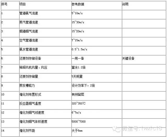
4 Design reference parameters of SCR denitration process in glass kiln
According to the engineering experience, the SCR reactor of glass furnace generally refers to the following parameters.
With the improvement of national environmental protection requirements for the glass industry, the environmental protection demand of the glass industry is expanding, and the first half of 14 years will also be the first concentrated outbreak period. Although the existing denitration, dust removal, desulfurization and other technologies are widely used in other industries, glass denitration will be developed rapidly with the introduction of thermal power denitration technology and special optimization according to the unique working conditions of glass kiln.

